
Firmen im Artikel

The protection principle behind the Ex i type of protection is based on limiting the energy that is conducted to the potentially explosive area and that can be stored there. This means that the energy from any potential spark has to be always less than the minimum ignition energy of the surrounding potentially explosive atmosphere. In
addition, no impermissibly hot and thus
ignitable surfaces – for example on electronic components – may be created. As opposed to all the other types of protection,
Ex i refers not only to a single item of equipment but to the entire intrinsically safe circuit, in accordance with IEC/EN 60079-11.
Ex i isolators are mandatory
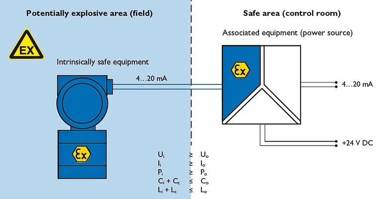
Intrinsically safe circuits are generally composed of the following elements:
- The intrinsically safe equipment, i.e., a load installed in the Ex area (Figure 1), e. g. an Ex i field device, where all circuits are intrinsically safe
- The associated equipment, i.e. a source installed in the non-Ex area (Ex i isolator), which contains both intrinsically safe and non-intrinsically safe circuits
- The connecting line (cable)
Ex i isolators are particularly important here. In accordance with IEC/EN 60079-11, they have to be designed in such a way that the non-intrinsically safe circuits cannot adversely affect the intrinsically safe circuits, including by means of safe electrical isolation. Ex i isolators are therefore mandatory in every Ex i MCR circuit. Moreover, they limit the energy conducted to the Ex area, i.e. the maximum no-load voltage Uo, the maximum short-circuit current Io and the maximum power Po, to a non-incendive level. At the same time, via Co and Lo, the Ex i isolators determine which maximum energy storage elements – concentrated capacitance Ci and concentrated inductance Li in the field device, line capacitances Cc and line inductances Lc – can be connected without jeopardising the intrinsic safety of the circuit.
Another important aspect of the Ex i type of protection is the reliability of the energy limitation itself under the assumption that certain faults will occur. For that reason, intrinsically safe electrical equipment and the Ex i-related switching parts of the associated equipment are designed in accordance with the required safety and divided into different protection levels, which in turn correspond with the different zones in the Ex area. The Ex ia protection level (double-fault tolerance) is suitable for use in zone 0, the Ex ib protection level (single-fault tolerance) is suitable for use in zone 1 and the Ex ic protection level (zero-fault tolerance) is only suitable for use in zone 2. The following applies accordingly to areas at risk of explosion due to dust-air mixtures (zones 20 to 22).
The proof of intrinsic safety
To ensure that the respective connection cannot produce incendive sparks and incendive hot surfaces, the user or system operator has to demonstrate and document “proof of intrinsic safety” in accordance with the so-called operator standard IEC/EN 60079-14. This process offers the user the advantage of being able to select and combine Ex i field devices and isolators from different manufacturers in accordance with the specific requirements.
Figure 2 shows a typical intrinsically safe circuit consisting of an associated item of equipment (source) with a linear or ohmic source characteristic curve, an intrinsically safe item of equipment, and the connecting cables. Also listed are the safety-related
parameters needed to demonstrate intrinsic safety and the criteria required for compliance with intrinsic safety. For safe use, these parameters must be able to be taken from the user documentation.
Observing the 50-percent rule
In accordance with the current versions of IEC/EN 60079-11 and IEC/EN 60079-14, an evaluation must also be carried out to determine whether the 50-percent rule must be used. This is because the certified Co and Lo values for the associated equipment may only be fully utilised in simple intrinsically safe circuits with no concentrated capacitances (= Ci) and no concentrated inductances (= Li) and in a mixed intrinsically safe circuit with concentrated capacitances and/or concentrated inductances on condition that Li 1 % of Lo or Ci 1 % of Co. If in the mixed intrinsically safe circuit Li ≥1 % of Lo and Ci ≥1 % of Co, the specified Co and Lo values must be reduced by 50 % for the verification calculation. The following then applies here:
- Ci + CC ≤0,5 Co
- Li + LC ≤0,5 Lo
To avoid this general reduction and to achieve the greatest possible flexibility, for some products – such as the MACX MCR-EX product line – specially determined additional Co and Lo value pairs certified by notified bodies are available, which can be greater by a factor of 1.5 than the halved values according to the 50-percent rule.
Explanation using an example
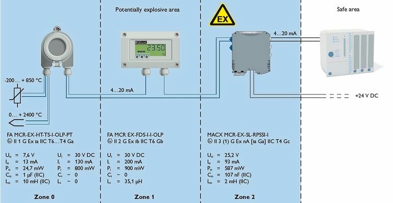
In process engineering applications, process variables such as temperature, pressure, flow rate, moisture, or pH value in the Ex area are collected by intrinsically safe measuring transducers (transmitters) and converted into a 4…20 mA standard electrical signal. Of these, temperature is certainly one of the most frequently measured physical variables. For that reason, we have provided an example showing how to verify the intrinsic safety of an intrinsically safe temperature measurement circuit which is led into a frequently occurring Ex atmosphere consisting of a hydrogen/air mixture (zone 0).
This Ex i measurement circuit consists of an interconnection between a MACX MCR-EX-RPSSI-I repeater power supply as the active associated equipment item with a linear source characteristic curve and two passive intrinsically safe items of equipment: an FA MCR EX-HT-TS-I-OLP temperature transmitter and an FA MCR-EX-DS-I-I process indicator (Figure 3).
For the verification of intrinsic safety, the following criteria must be fulfilled:
- The device protection level (Ex ia, Ex ib, nA [Ex ia]) or the device category (1G, 2G, 3(1)G) is suitable for use in the corresponding zone. This criterion in the example is met by the indication in the EU examination certificate for the field display that the device can be used within an Ex i circuit with ia protection level without this affecting its level of protection.
- The explosion group is suitable for the application. All Ex i devices used apply according to the marking IIC for an Ex atmosphere consisting of a hydrogen-air mixture.
- The temperature class is suitable for the application. All Ex i devices used have a temperature class between T4 and T6, depending on the permissible ambient temperature, and are therefore suitable for a hydrogen-air mixture.
- The five criteria listed in figure 2 regarding the Ex i parameters are met. This prerequisite is met in accordance with the Ex i parameters shown in figure 3. This is a mixed Ex i circuit for which there is no need to use the 50-percent rule. Only the process indicator has an inductance of 35.1 μH to be considered. Assuming a specific cable capacitance Cc of 140 nF/km and a cable inductance Lc of 1 mH/km, a maximum cable length of 750 m for the capacitance and 1964.9 m for the inductance is thus mathematically possible with a Co value of 107 nF and a Lo value of 2 mH. Since the smaller value is decisive, this interconnection is intrinsically safe with a line length of up to 750 m.
The proof of intrinsic safety described above must be implemented separately for the interconnection of the field-side connections of the head-mounted transducer with the thermocouple and the resistance thermometer. Thermocouples and resistance thermometers are considered “simple electrical equipment” as defined in IEC/EN 60079-11 and IEC/EN 60079-14.
Consideration of functional data
When choosing devices, the dimensioning of the functional data must be taken into consideration along with the proof of intrinsic safety. For example, the MACX MCR-EX-SL-RPSSI-I repeater power supply provides the FA MCR EX-HAT-TS-I-OLP temperature transmitter with a supply voltage of 16 V at 20 mA. The temperature transmitter in turn requires a supply voltage of at least 11 V DC. The slight voltage drop for the FA MCR EX-DS-I-I process indicator of 1 V (1.9 V with Hart) proves beneficial, because the supply voltage for Ex i sources is smaller than for non-Ex i devices. Therefore, 3.1 V are still available for a line-related voltage drop and as a reserve.
Approvals for maximum flexibility
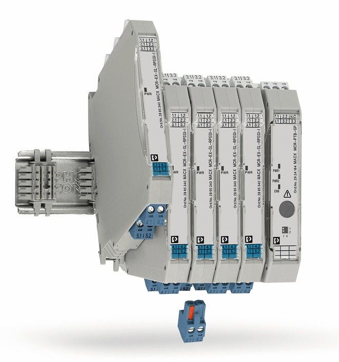
Innovative Ex i isolator series such as the narrow 12.5 mm single- and two-channel MACX MCR-EX-SL stand out, thanks to their optimally coordinated Io, Uo, and Po values, making them compatible with a large number of Ex i field devices. While developing the product family, importance was also placed on the highest possible Co values, given that this is an essential parameter for determining the maximum viable cable length (Figure 4).
The Ex i isolators of the comprehensive MACX MCR-Ex series are approved for use in explosion protection in accordance with
directive 2014/34/EU using harmonised standards. In accordance with the Ex II(1)G [Ex ia Ga]IIC and Ex II(1)D [Ex ia Da]IIIC markings for Ex i circuits up to Ex zone 0 (gas) and Ex zone 20 (dust), they can be used for all Ex zones as well as all substance groups, which means a high degree of flexibility. Furthermore, MACX devices can be installed in Ex zone 2 in accordance with Ex n and Ex ec type of protection, which makes them easier to use in distributed automation concepts. Other international approvals such as IECEx, EACEx, or UL HazLoc are prerequisites for their use in applications across the globe.
Phoenix Contact GmbH & Co. KG, Blomberg

Author: Heinrich Käuper
Product Manager Analog Ex,
Phoenix Contact Electronics


