Non-experts would assume that flow – and thus turnover – is the decisive parameter in oil production. Professionals, on the other hand, know that pressure is the key factor. Hydrostatic pressure, formation pressure, overburden pressure as well as system pressure loss – oil well control is for the most part pressure control and therefore always safety relevant.
Not only directly at the well, but also for downstream process equipment, pipelines, wellhead flowlines or gas manifolds overpressure protection must be guaranteed. Hipps are installed to provide overpressure protection for process equipment in the upstream and downstream. To avert overpressure scenarios or minimise their associated consequences, Hipps could be used to isolate, reduce, or divert sources of overpressure, thereby avoiding equipment damage and loss of containment. While a relief system aims at removing any excess inflow, a Hipps aims at stopping the inflow of excess fluids and thus avoiding over-pressure. The addition of a Hipps can help reduce the probability of excessive load on an existing conventional pressure relief system and eliminate the high costs associated with purchasing new relief devices, resizing existing flare headers, re-rating flare knock out drums, redesigning the flare stack, etc. Also it provides the opportunity to minimise costs due to loss of operations.
The reliability of a doorman system
Hipps is a safeguard system that is designed and built in accordance with the IEC 61508 and IEC 61511 standards. As a complete functional loop, or Safety Instrumented Function (SIF), it usually consists of initiators, a logic solver and the final elements. Nowadays, most initiators are electronic. Their job is to detect the high pressure. The logic solver processes the input from the initiators to an output to the final elements that actually perform the corrective actions in the field by bringing the process to a safe state. Typically three sensors are connected to the logic solver, which is configured to vote with a 2oo3 logic. This configuration is preferred for Hipps, since it provides availability as well as reliability for the system.
But how can one calculate the performance of a doorman system that only acts when needed and otherwise remains inactive? Here it is to our advantage that IEC 61511 is a performance based standard and not a prescriptive standard. It indicates how to determine requirements and achieve and maintain performance of Safety Instrumented Functions over the whole life cycle of the plant (from the cradle to the grave). It defines levels of performance based on the risk reduction they provide. According to the risk reduction the safety level is defined as Safety Integrity Level. The Safety Integrity Levels range from 1 to 4 and are a quantitative target for measuring the level of performance needed for a safety function to achieve a tolerable risk for a process hazard. For an “on-demand” doorman application such as a Hipps, the SIL defines the average probability of failure demand (PFDavg). The higher the SIL level, the higher the associated safety level and the lower the probability that a system will fail to protect.
Now this system is not a static one: over the time, the availability as well as the probability of failure change, which makes regular health checks, i.e. inspection and testing necessary. And that means effort, which should not be underestimated: to increase the performance of a SIF, let’s say from SIL 2 to SIL 3, it must be tested ten times more often or – as other design factors such as Hardware Fault Tolerance (HFT) and systematic capabilities must be considered too – the SIF has to be designed to have ten times less dangerous undetected failures. With this in mind, it is hardly surprising that the design of such SIFs quickly becomes very complicated. On the other hand, one must take into account that security is another factor to take into consideration on top of functional safety.
An application example
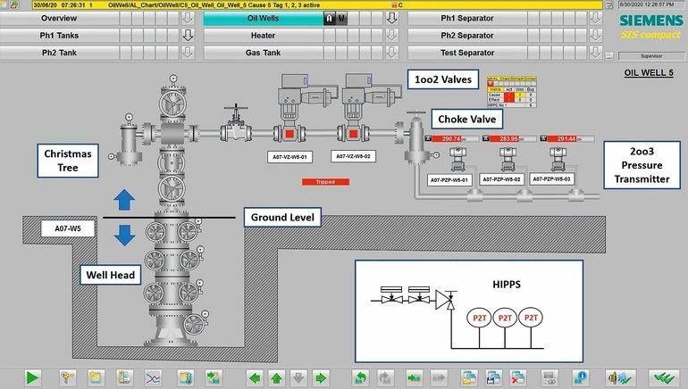
How do you get such complexity under control? How can you set up a safe system for an oil field that normally consists of more than one well, and where besides reliability also cost efficiency plays a major role? Imagine an application that consists of an oil field with nine wells connected to a flow station which conditions the crude oil so that waste of energy pumping undesirable components such as water is avoided as much as possible. The intake in the well head is round about 350 bar (≈5,000 Psi), so the pressure needs to be reduced at the Christmas tree to a more manageable range (20 bar, 250 to 300 Psi) by a choke valve. To avoid the pressure downstream will elevate to the wellhead value, braking seals and loosing containment (spilling crude and releasing gas) for instance by blockages or operating errors, a Hipps is installed in each Christmas tree. Both Hipps valves (in architecture 1oo2) are “de-energised” to trip self-contained hydraulic valves with oil pumps onboard, which would isolate the well and protect the downstream pipeline. Beyond that the safeguard would also have to perform other tasks: control and protection of the flow station, especially monitoring the manifold, the separator as well as connected storage tanks. In total, a good 250 I/O signals and another 100 signals per well would be combined.
The solution and its benefits
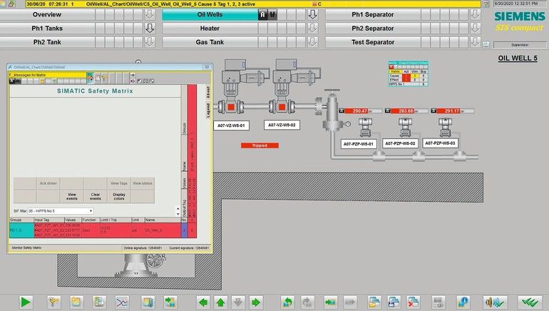
How high do you estimate the automation effort that is necessary to safely monitor and operate this application? In fact, this requires exactly one Simatic SIS compact in redundant design. Simatic SIS compact was designed by Siemens as a stand-alone Safety Instrumented System (SIS) based on the Simatic product portfolio. In order to recognize safety-critical procedures, the system supports the Syslog network protocol for transmitting log messages. A very precise time stamping mechanism serves to acquire and analyse the chronological sequence of events in resolution of 5 ms. For the comfortable creation of standard- and safety-oriented functions, SIS compact is compatible with Simatic Safety Matrix. Use this TÜV-certified Safety Lifecycle Management tool for the efficient engineering of safety applications up to SIL 3 in accordance with IEC 61508 as well as for their simple operation and monitoring. This enables the operator the monitoring of active variables out of safe operational range as well as field signal quality monitoring (e. g. maximum hysteresis).
In our example application, the certified safety system Simatic SIS compact is providing a SIL 3 solution (depending on the SIF) and an independent (certified interference free) Control System in one controller for control loops associated to a particular hazard, like pumps control. The redundant configuration allows to have high reliability, since redundancy is not needed for safety performance but rather for availability.
With Simatic SIS compact, very simple architectures can be used to solve quite complicated tasks in a very flexible way. The result is a cost-effective and easy-to-install solution that can be easily adapted to specific requirements. Customers can choose architectures with two sets of redundant controllers, depending on required performance. In addition, Simatic SIS compact could be used in other applications doing safety and control in one and the same system, e. g. burner management as allowed by the latest NFPA 85 for a single burner (as a Burner Management System – BMS), small reactors, tank farming. But also the communication to a dedicated control system with Modbus/TCP is supported.
The solution based on Simatic SIS compact offers a flexible solution based on the well-known Flexible Modular Redundancy (FMR) of the Simatic PCS 7 safety solution with the choice of an integrated control and operating system or a dedicated safety system with a connection to a separate control and operating system, using Modbus/TCP.
Online search: Siemens

Author: Thomas Bartsch
Sales Development Manager,
Siemens Digital Industries


