Facilities manufacturing polyolefin resins rely on a myriad of additives and sophi-sticated chemical formulations to produce polymers with varied performance capabilities. As such, these facilities face numerous engineering challenges associated with the handling of very different and demanding materials. Proper selection of equipment and the related controls are essential. Finding the right partner can help reduce problems and save money.
The author: Dr. Jaime Gomez Business Development Manager Plastics, K-Tron (Switzerland)
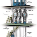
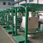
Materials used in the production of polyolefins, such as polyethylene, polypropylene, ethyl vinyl acetate and others, may be abrasive, friable, sticky, moisture and temperature sensitive, hazardous, hard-to-filter or oxidation-prone. In addition, the flow characteristics can cause problems concerning poorly flowing raw materials, powdered additives and finished pellets. Proper selection and implementation of bulk solids handling components and controls (Figure 1) can help polyolefin manufacturers to increase plant yield and reduce excessive downtime or lost production as well as labour, material and energy costs, thereby minimising engineering problems while improving overall long-term profitability. Choosing an engineering partner with broad equipment offerings, industrial experience and technical know-how is key. With over 100 years of experience, K-Tron has broad expertise in the polyolefins sector as well as a strategically oriented portfolio. Although the components and controls discussed below were installed as part of a given polyolefins facility, the discussion is relevant for all such facilities.
Engineering the dry-end process
During manufacturing, polyolefins are produced upstream in a wet-end process and the resulting polymer resins (typically in the form of cleaned fluff or flake) are sent to the dry-end process for compounding with various additives. The clean, dry powder is then transferred pneumatically with nitrogen (to prevent oxidation) to an intermediate storage or powder surge hopper that is situated several levels above a melt extruder.
During upstream polymerisation, lumps can form in the polymerisation reactor. To avoid problems in the dry-end process, these lumps must be eliminated. The EDK rotary feeder has a double-knife arrangement, double helix blades and a specific number of pocket dividers. The feeder shears lumps as they pass through during operation. The largest EDK unit can handle over 350 m3/h (12,360 ft3/hr).
Primary resin feeding
Three types of gravimetric feeders are commonly used to measure and control the rate of the primary resin being delivered to the dry-end process:
- Smart mass flow meters with rotary valve or EDK pre-feeders
- Large loss-in-weight (LIW) feeders
- Large weigh belt feeders
A smart flow meter (KSFM) located below the rotary feeder or EDK delumper monitors and controls the flow of the polyolefin resin. To ease maintenance, an additional, manually operated slide-gate shutoff valve may be installed upstream of the rotary valve or EDK. The KSFM – which has no moving parts – includes two weighing units mounted inside a cylindrical body. During operation, the KCM control mod-ule uses signals from these two sensors to compute the actual mass flow rate, compare it with the desired setpoint and adjust the rotary pre-feeder speed to maintain the latter.
The system can also function as a mass flow meter, where the rotary pre-feeder runs at a constant speed and the KCM computes the actual mass flow of the polymer. The throughput provides the master rate signal for controlling the rest of the additive feeders in the line. Each additive is then proportioned into the process as a function of the flow rate.
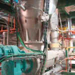
With some polyolefin grades, the use of a large LIW feeder (Figure 2) is preferred. In this scenario, a large surge hopper is supported on three or more KSFT digital load cells with a screw feeder attached to the bottom. A KCM controller monitors the weight loss of resin within the hopper, calculates the actual mass flow, compares it with a desired set rate and controls the speed of the feeder to maintain this setpoint. A fast-acting slide-gate valve mounted above the LWF feeder is activated by the KCM feeder controller. This manages the flow of material into the LWF hopper during the refill cycle. An additional, manual slide-gate shutoff valve can be installed ahead of the slide-gate valve to ease maintenance. If a significant turndown in feed rates is required, a secondary, smaller-diameter feed screw can be mounted parallel to the primary screw. The KCM automatically detects whether one or both screws are running and adjusts their speed to maintain the desired rate of resin flow.
In applications where there is not sufficient headroom, the smart weigh belt feeder is a third alternative. This gravimetric feeder, with its enclosed stainless steel frame and conveyor assembly, is typically interfaced to an upstream rotary valve or EDK pre-feeder. In this scenario, the weight of the resin is measured as it passes across the belt using KSFT digital load cells. The KCM controller monitors this weight, calculates the actual mass flow of resin, compares this actual rate with a desired rate and adjusts the belt speed to maintain the latter. As with the K-Tron smart flow meter, the pre-feeder speed can be controlled by the smart weigh belt feeder’s KCM to maintain a desired flow rate at the inlet.
Alternatively, the smart weigh belt can function as a weigh meter and simply monitor the rate of polyolefins being produced and fed into the downstream process. In either control concept, the KCM controller provides a master polyolefin flow rate signal that is used to adjust all additive feeders.
Blending additives into the matrix
During polyolefin production, any number of functional additives – such as stabilisation agents, anti-oxidants, calcium and zinc stearates, slip additives, anti-block agents or processing aids – are blended into the resin to help the final polymer achieve specific performance capabilities. This requires the use of specialised equipment, such as bag unloader stations fitted with paddles or rams that help break agglomerates and stimulate material flow, dump stations to handle smaller bags (Figure 3), bin vents, discharge valves, feeders and more. The discharge of powdered additives into surge hoppers and storage tanks creates airborne dust that must be contained. Bin vents – including automatic, modular and static designs – are mounted on top of the surge hopper to capture airborne dust particles.
As additives are transferred from bulk bag unloading stations into surge or storage hoppers and then fed into LIW feeders, the various equipment components must alternate between recharge and discharge modes to ensure that additives are available without interruption. Depending on the nature of the additives, different feeder options are possible, including single-screw feeders, twin-screw feeders, vibratory trays for fibrous materials, small belt feeders and bulk solids pumps (BSP). Similarly, different hopper sizes, capacities and configurations (including cylindrical, asymmetrical and symmetrical shapes) can be selected, while specialised hoppers can provide mechanical vertical agitation or be equipped with an ActiFlow non-product-contact activator.
The weighing system can range from small-capacity platform scales to large, three-point suspension scale systems. All weighing systems employ patented, digital K-SFT weighing technology with 1:4,000,000 in 80 ms weighing resolution as well as vibration and temperature drift immunity. For liquid additives, many loss-in-weight pump configurations exist with liquid tanks that can be heated or cooled. In addition, liquids can be controlled using a flow meter and PID controller.
Dispersive and distributive mixing
Blending small amounts of additives into a high rate stream of polyolefin resin presents a variety of challenges. Two styles of mixing occur – dispersive and distributive – and it is essential to optimise both.
If additives are allowed to agglomerate or spread unevenly throughout the resin, the final compounded product will suffer from uniformity problems. The goal is to produce a compounded mixture that has both good dispersion and good distribution of the additives. Screw conveyors with flight variations that provide back-mixing, which are sealed and under slight nitrogen pressure to prevent the oxidation of the polyolefin, are installed upstream of the melt extruder. They evenly mix small amounts of additives into a large amount of polyolefin resin before the mixture enters the melt extruder. Additives are typically dispersed through numerous inlets along the entire length of the screw conveyor.
As mentioned earlier, the extruder melts, mixes and extrudes the mixture of polyolefin and additives so that it can be pelletised. After this operation, a pressure-conveying system is used to move the polymer pellets to a product storage vessel and, if needed, a blending silo. Homogenisation is achieved by circulating the pellets from the bottom to the top part of this silo with a pneumatic conveying system and preventing the hot pellets from settling (to reduce clump formation). The Premier ProBlend zone blender blends and homogenises any free-flowing bulk materials in a hopper or silo. Thanks to its special geometry, the device provides ten different flow zones that allow the material to pass through the silo at different velocities and residence times. This ensures that the discharge stream contains a blend of materials from throughout the silo or hopper.
From the blending silo, the pellets are pneumatically transferred to load-out area silos via a vacuum or pressure-conveying system. To reduce the formation of fines and floss (such as angel hair, fluff, snakeskins, streamers, threads and ribbons) during pneumatic transport, positive pressure systems with air coolers can be installed to reduce heat build-up. At the end of the line, the finished pellets are typically gravity-fed into bulk-transport containers such as rail hopper cars and bulk hopper trucks or packaged in boxes, supersacks or bags. A smart flow meter is used to meter the materials.
Process controls
Each part of the dry-section process – such as the polymer feed system, the additive supply systems and the screw conveyors/homogenisers – has one or more sub-control modules (typically a programmable logic controller or PLC) and its own interface with the controls for both the upstream wet-end process and the downstream extruder. These PLCs obtain their direction from the central, plant-wide distributed control system (DCS).
Each ingredient feeder is supplied with a dedicated KCM, which guarantees that the material is delivered into the process as precisely as possible and within specified tolerance levels. A process line operator interface, called K-Vision, allows an interface with up to 16 ingredient controls to be monitored from a single point. For multiple extrusion lines with multiple feeders in each line, a KSC smart commander – which is capable of interfacing with up to 30 feeders or devices in one to eight extrusion lines – can be used as the operator interface.
Online-Info: www.cpp-net.com/2111463
Share:
