Over the past few years, the use of dry disconnect couplings for loading and logistics processes in the fluids sector has become the rule rather than the exception. While the need for this safety technology is generally no longer questioned, the focus is now on the performance of the particular coupling used. The consequence: users and manufacturers are confronted with an increasing degree of product differentiation. This is being driven by the potential for efficiency in all areas of the application process.
Author Dr. Jens Reppenhagen Managing Director, RS Roman Seliger
Dry disconnect couplings facilitate quick coupling and decoupling of hoses and pipelines at mobile and stationary tanks or vessels without any significant leakage or loss of the fluid being handled. In this way, they protect people, the environment and materials from coming into contact with caustic, toxic or explosive media, for example. For this purpose, they are equipped with the following basic functions:
- Sealing mechanism for both coupling halves in the uncoupled state
- Sealed connection of the coupling halves in the coupled state
- Mandatory sequences (coupling: sealed connection of the coupling halves before the sealing mechanisms are opened, decoupling: coupling halves are closed and sealed before they are separated)
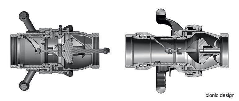
Apart from numerous special solutions, there are two major technologies which are differentiated primarily based on the sealing mechanisms, i. e.:
- Couplings with ball-type check valves similar to ball valves that guarantee a free flow cross-section
- Couplings with disc valves vertically positioned relative to the flow direction
In contrast to disc valves, ball valve technology offers the advantage that dry coupling safety is not achieved at the price of a pressure drop (lower flow rate). Furthermore, it can cope with large foreign bodies. However, the higher investment costs, expensive spare parts and significantly greater susceptibility to minor levels of contamination as well as poorer ergonomics substantially curtail the useful fields of application compared to disc valve technology.
The dynamics of current technological developments therefore focus on the diverse range of designs employed in disc valve technology. As regards basic functionality, there are two closely interlinked differentiating characteristics in this context: the geometry of the two coupling halves relative to one another (referred to as the interface) and the kinematics used to actuate the disc valves. The interface often plays a key role in the operator’s choice. Whenever mobile units (containers, tankers, rail tank cars, etc.) are involved, the compatibility of all loading and unloading stations must be guaranteed – which means that the same interface must be available. Beyond the realms of clearly defined closed circuits, a standardised interface is therefore essential. The bayonet principle according to Stanag 3756 has consequently established itself worldwide and, despite several good alternative technologies, captured by far the largest share of the market for dry disconnect couplings – a market that is supplied by a growing number of manufacturers.
Stanag dry disconnect couplings consist of two halves (male and female), each of which is equipped with a disc shut-off valve. Coupling is performed by pushing/inserting the male half axially into the female half. A rotary motion creates a sealed connection between the two coupling halves. Further rotation by approximately 100 ° opens the valves by transmitting a sliding action into the centre of the male section, which opens a ring-shaped flow channel. During the uncoupling operation, the rotatory movement is performed in the opposite direction: the flow channel in both coupling halves is sealed before these halves can be separated.
This principle has proven its effectiveness for more than two decades, although throughout this period only the production processes have been optimised and not the products themselves. The design has remained practically unchanged. Increasing demand is now attracting new players to a market in which competitive pressure forces them to contribute to the current dynamic pace of product optimisation. Although the interface and associated basic kinematics have been retained, we are now seeing the emergence of completely new generations of Stanag dry disconnect couplings which offer significant added value compared to previous products.
Focus on efficiency
In modern coupling technologies, all parts that come into contact with fluids are flow-opti-mised and increasingly resemble bionic forms. The primary beneficiaries of these developments are all time-critical loading processes, particularly those used in the offshore sector or for loading and fuelling ships. This advantage also pays dividends with railway tank cars and tanker trucks – especially in the case of gravity discharging without the support of pumps. In scenarios such as these, the bionic design of the new generation can reduce loading times by up to a half with the same diameter compared to traditional products.
In the latest generation of couplings, great importance is attached to optimised assembly and disassembly times. Modular design of the functional units is the method of choice for achieving this. Put simply, this means that all parts are designed as far as possible to be assembled without specialist expertise and with only a minimum of tools. In the most recent concept, the coupling no longer even needs to be unscrewed from the hose or pipe to enable replacements of wear parts such as O-ring seals. If necessary, on-site servicing can also be carried out in a matter of seconds directly in the application rather than having to first completely dismantle the unit at an authorised workshop, as was the case with previous coupling generations. This saves precious time and avoids system downtime, thus providing maximum flexibility.
Even in situations where it is impossible to reduce the level of wear, the resulting costs for wear parts are significantly lower in the new generation. Whereas in the past attempts have been made to accommodate all functions in as few components as possible, the current state of the art is to distribute critical wear areas across individual parts wherever feasible. A good example of this is the control cams used in female parts: in older generations, these are integrated in the housing in such a way that a worn coupling must basically be disposed of. By contrast, some of the new-generation types feature a control cam insert that allows the cams to be replaced quickly in the field in just a few simple steps. The substantial savings in outlay for spare parts and maintenance are a great advantage here.
Reduced costs for sealing
A significant and rapidly growing share of couplings are currently fitted with expensive FFKM O-rings due to their chemical resistance properties. Depending on the diameter and compound, this can lead to a doubling of the price for conventional sealing technology in older coupling generations compared to FKM couplings – a very relevant aspect in view of the fact that each female part (hose unit) is traditionally provided with four O-rings that are in contact with the medium. In many of the new-generation types, it has been possible to halve the number of O-rings and, therefore, the additional costs. Both investment and, above all, maintenance spending are much lower as a result – and each replacement now costs only half as much.
Optimised ergonomics
The process of actuating the coupling needs to be made as easy as possible. The parts of the new-generation types that are responsible for the coupling kinematics are therefore designed in such a way that the limited manual force is introduced into the coupling as effectively as possible for the purpose of actuating the valves.
The control cams make a critical contribution in this regard, in terms of both their profile and their manufacturing precision. In modern couplings, the profile may even require modular adaptation to the respective application. With the control cam inserts mentioned above, this can be offered in a way that is not only simple but also far more cost-effective than if the cams are integrated in the housing. The advantages of an optimised control cam come into play when coupling against high pressures and especially with large diameters. Some of the new-generation couplings can handle significantly higher pressures – regardless of whether the male, female or both parts are pressurised. Optimised control cams also provide another benefit: when older-generation female parts are fitted to the male part, the operator must apply considerable force while pressing them together simply to continue coupling. The new generation of control cams eliminates the need for axial forces and instead transmits them from the first part of the rotary movement. In practical use with the load imposed by the hose, this is particularly worthwhile with diameters of 3 ” or more. The operator simply has to concentrate on holding the weight of the female part and hose, positioning the coupling and then initiating the rotary motion. An additional axial force, which can often only be produced by the operator’s own body weight, is no longer required.
The design of the swivel joint also has a major influence on the actuating forces: a high level of radial stress resistance provided by double ball paths, combined with low levels of friction thanks to the use of suitable seals, reduces these forces – especially with large diameters and high pressures. These advantages are achieved in modern couplings through a process of functional separation, where the swivel joint is no longer also used to cover the housing as it was in previous generations.
The handles for the new concepts have been ergonomically designed, not just to fit comfortably in the hand but also to guarantee excellent force transmission in every coupling position. The position of the handles is likewise important: they should not block the view of the separation point and it should be possible to continue holding the coupling horizontally even with the hose attached. Furthermore, the grip on the handles or the grip surface with small diameters should be designed to guarantee safe operation of the coupling even if the operator is wearing wet gloves.
Optional locking function
To prevent errors and provide feedback during coupling, operators are increasingly requesting a locking function. A locking mechanism ensures a secure coupling connection during loading. This also means that forces transmitted via the hose cannot accidentally release the coupling connection. Decoupling must be deliberately initiated by the operator using the release.
The coupling should therefore be designed so that this type of function can be implemented without any major effort and if necessary retrofitted.
Hall 8.0, Booth L68
cpp-net.com/0215408
Share:


