For an ever widening range of previously hard-to-measure products such as molten sulphur, liquid ammonia and petrochemicals, guided-wave radar transmitters provide accurate level measurements even in harsh chemical environments or with wide variations in operating temperatures and pressures as well as low dielectric constants. Due to their straightforward design and lower operating frequency, guided-wave units are also often less expensive than comparable through-air units.
Eric Fauveau, Kevin Hambrice
Great strides have been achieved in making these units easier to configure to a variety of process applications, coupled with the simplicity of integrating these devices with most digital communication protocols. These improvements come as welcome relief to process engineers in a wide range of level applications spanning several different industries, as they seek solutions for measuring the contents of tanks, silos, hoppers, bins, mixing basins and vessels.
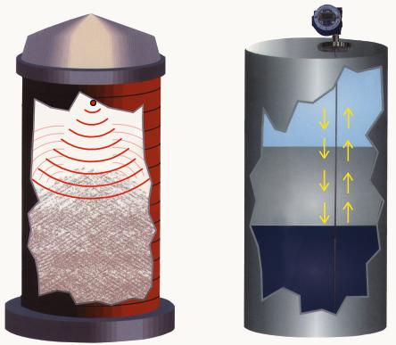
As radar transmitters have no moving parts, radar has already established a dominant niche in level measuring, setting itself apart from mechanical means which do not hold up as well in dirty service. Radar achieves its non-mechanical level detection capability by measuring the time of flight of the transmitted signal.
Referred to more accurately as time domain reflectometry (TDR), this process involves sending microwave energy down into a vessel. When the pulse of radar energy reaches the product (indicated by a change in impedance), part of it is reflected back towards the transmitter. A receiver measures the exact time between the transmitted and reflected signals – the time of flight. The device analyses this time and ultimately displays the level of the product as a distance in feet, metres or another engineering unit.
Performance and reliability
In conjunction with additional parameters, such as the reflectivity of the inside walls of a vessel or internal tank obstructions (i.e. piping, nozzles, ladders, etc.), a laptop is often required to configure a through-air instrument in order to yield an accurate reading of product level. Additionally, non-contact radar units are very sensitive to changes in the process conditions, such as product build-up or condensation. Similarly, ultrasound remains highly vulnerable to tank conditions and vapour phases, which can affect the speed of sound. If not set up properly at the receiver, varying and inaccurate readings can result. On the other hand, the basic theory behind guided-wave radar helps prevent false echoes.
Overcoming the dielectric obstacle
Obtaining accurate readings in products with a low dielectric constant provides the greatest challenge to most radar transmitters, as it becomes increasingly difficult to obtain a reflected signal. Radar waves partially pass through non-conductive materials like liquid propane or butane, making it traditionally problematic to measure levels exactly.
In both guided-wave and through-air radar, the coax cable that carries the signal from the transmitter to the process connection typically has an impedance of 50 In both guided-wave and through-air radar, the coax cable that carries the signal from the transmitter to the process connection typically has an impedance of 50 .. Ideally, if one could maintain that same impedance along the entire length of travel of the radar beam, then all the reflected signal would bounce off of the product. In actual fact, however, a large impedance change occurs at the transition from coax to air, leading to a substantial loss of signal.
Guided-wave radar sidesteps the challenge of measuring low dielectrics by using a single probe protected by a stainless steel tube that functions like a small concentric shield surrounding the entire probe length, thereby giving the whole assembly a coaxial structure. The tube acts as a ground plane to help channel the energy. It maintains a constant impedance along the complete wave-guide. The coaxial sensor can then detect more subtle dielectric changes and correctly indicate the level of the product. Through-air radar can also use a similar pipe arrangement to channel energy and measure lower dielectrics. However, with through-air radar this mode of operation is much more susceptible to build-up and is very dependent on the pipe configuration and design.
Measuring long spans
Modern radar transmitters are nowadays capable of measuring the levels of very tall silos and tanks. Some radar transmitters are designed to cover distances greater than 60 m. Usually, however, it is extremely difficult to obtain high-resolution readings over such a wide range.
Some guided-wave radar and through-air transmitters utilise special electronic circuitry that includes very stable ramp generators. These generate a signal waveform that duplicates the reflected waveform, albeit in a much slower time frame. Only highly stable and accurate electronics can obtain resolution levels in the region of a few ten thousandths of an inch over a whole span – sufficiently accurate to meet the needs of almost any application.
However, guided-wave radar offers a clear advantage over through-air since the microwave energy is focused and travels along the waveguide, making this technology much more suitable for long measuring lengths particularly with low dielectric products.
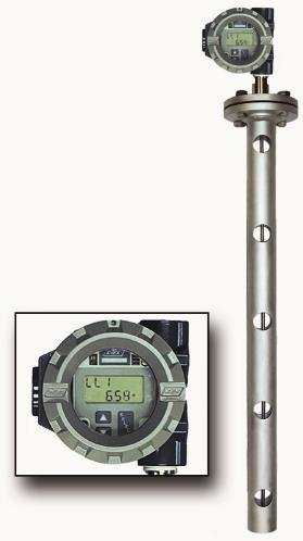
MT2000 guided-wave radar
K-Tek’s MT2000 offers the traditional advantages of radar level measurement, such as measuring both liquids and solids, with no moving parts. Yet the MT2000 goes one step further by employing a metallic probe to effectively act as a waveguide that directs the microwave pulses, thus eliminating the beam divergence common to conventional non-contact radar transmitters. Since the MT2000 has no beam divergence, there are also no false signals or echoes from objects other than the product surface, and there is no need to spend many hours programming the unit to ignore erroneous readings from the sides of the tank or other internal structures. Setting up the MT2000 is easily accomplished via onboard pushbuttons – no laptop computer or special software is required. The MT2000’s probe can be cut to size in the field from 2 to 100 feet (0.6 to 30.5 m), and can even operate when bent in many applications.
cpp 442
Share:


