Crude oil and gas that is extracted from underground deposits must be chemically processed to form compounds from the mixture of different hydrocarbons. The two main stages in this process are refining and cracking. Fractional distillation involves a mixture of substances being separated into their components, whereas cracking involves chemical processes taking place. Deviations from the process sequence in petrochemical plants often represent dangerous errors. Petrochemical processes automatically require SIL 3. Major control system manufacturers only list suppliers of interface products if the entire portfolio is suitable for use in SIL 3 applications and has also been tested accordingly.
The principles of functional safety are set out in IEC/EN 61508, which was first published in 1998. Edition 2 was published in 2010. IEC 61511 describes the principles of functional safety for safety instrumented systems in the process industry and is derived from IEC/EN 61508. Some trends in how these guidelines are implemented have been observed in recent years.
Field and interface devices with SIL suitability are increasingly being used where SIL suitability is not required by a risk assessment. Using a single, uniform device type simplifies storage and prevents confusion between devices with and without SIL suitability. Around two thirds of all interface devices delivered by Pepperl+Fuchs today feature SIL 2 or SIL 3 suitability.
Quick Shutdown
In the event of a critical operating state in the plants, the emergency shut down system (ESD) must stop the supply of material and vent the lines. Solenoid valves are often used for this purpose. Solenoid valves function as an upstream interface between the electrical control level and the pneumatic drive. They are operated by electromagnets and can switch very quickly. The electromagnets are controlled by solenoid drivers, which protect the intrinsically safe field circuit and establish galvanic isolation between the control panel and the intrinsically safe solenoid valve. Solenoid drivers prevent compatibility problems between the field device and the diagnostics of the digital output (DO) cards in the emergency shut down system. The user can fully utilise the diagnostics and protective features provided by the DO cards during operation, while the general safety function remains unaffected. These measures include test pulses with frequencies in the kHz range and a duration in the microsecond range; a specific load current in the on/off state, depending on the card and manufacturer; and a limitation of the inrush current to protect the DO card. Sensors monitor the shutdown. In addition, acoustic and visual warning systems, and fire extinguishing devices must be activated in an emergency. Safety relays are used to activate these systems.
With integrated diagnostics
To optimise the availability of the safety functions, Pepperl+Fuchs has developed a safety relay that includes fault monitoring in the switching elements, integrated diagnostics, and line fault detection for field-side short circuits and lead breakages. All contacts have been arranged redundantly to increase the availability of the safety functions. The design is based on MooN architecture, which means that M-out-of-N elements must be in an operating state.
Integrated diagnostics are performed using time-delayed switching of the elementary relays, with one relay checked during each switching operation. In ETS (energized-to-safe) circuits, all three relays of both contact groups are initially closed if three consecutive switching operations occur. During the delay period, the device checks whether this operation closes the circuit as a way of detecting a faulty contact. By changing the sequence for time-delayed switching, all contacts are checked after three switching operations. Diagnostic checks of DTS (de-energized-to-safe) circuits take place during the restart process rather than during shutdown. Initially, two relay contacts are closed simultaneously and the third contact is closed after a time delay. The idea is that there is no current flowing before this contact closes, otherwise this relay is faulty because it no longer disconnects the circuit. A different relay is checked during every switching cycle. The checks are typically carried out on an annual basis. The safety relay executes the routine described above once during these annual tests, and will have been fully tested after three years without any additional effort.
The line fault transparency feature provides seamless monitoring of voltage and load resistance. It detects field-side short circuits and lead breakages and can assign them to a specific signal circuit.
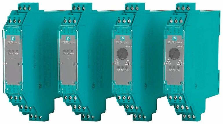
Thought was also given to the need for quick adjustments of the safety relay. The input circuit is identical for all devices. This means that once a device has been tested using one of the control panel’s DO cards, all other modules of the safety relays are compatible. The complete product family of the single-channel and loop-powered safety relay KFD2-RSH includes a total of four modules for DTS and ETS applications with either 24 V(DC9 or 230 V(AC). They are approved for Atex Zone 2, and comply with SIL 3 (IEC 61508 ed2) and PL e (EN/ISO 13849 for the DTS modules).
Extended test cycles
Operators are increasingly discussing extending the test cycles for safety devices. Operators should carefully consider the benefits and potential disadvantages of extended test cycles since systematic failures are frequently discovered during tests, such as the media incompatibility of field devices. Currently, attempts are being made to extend testing cycles from a typical one-year period to one of up to five years. Typically, a plant or plant part is shut down at specific intervals for maintenance purposes, instead of testing each device individually. The idea that the weakest link determines the strength of the chain applies in this scenario. All components used must be able to be incorporated into the desired maintenance cycle, i. e., each component must individually have a sufficiently long proof time.
Pepperl+Fuchs has responded to precisely this development by developing the safety relay with integrated diagnostics. Diagnosing the state of the elementary relays increases the proof times to well over ten years.
Redundant SIL 2 devices
In addition to the above-mentioned integrated diagnostics in devices, the redundant design of SIL 2 devices has become established in SIL 3 applications. This is permissible if systematic failures are excluded as far as possible. This can be ensured by heterogeneous redundancy. Homogeneous redundancy is also possible if the devices have systematic capability for SIL 3 applications. This systematic capability can be proven by a functional safety management (FSM) certificate. In cases where the Machinery Directive applies, the EMC standard EN 61326–3–1 also applies. According to this standard, the test duration must be increased by three to five times for some tests on an SIL 2 device if the device will be used for SIL 3 applications. However, this is not a requirement in the corresponding standard for the PA division, EMC standard EN 61326–3–2.
Pepperl+Fuchs AG, Mannheim, Germany

Autor: Andreas Grimsehl
Product Marketing Manager Interface Technology,
Pepperl+Fuchs


