By applying calorific value technology, operators of steam and hot water boiler systems can lower their running costs while helping to reduce CO2 emissions. Any additional investment required can often be recouped within less than two years by consistently utilising heat energy.
The energy contained in flue gas water vapour can be exploited using calorific value technology. Corrosion-resistant materials in heat exchangers and moisture-resistant flue gas systems and chimneys can facilitate this without causing long-term dam-age. In order to utilise calorific value, it is necessary to extract not only the tangible heat from the flue gas, but also part of the condensation heat bound in the vapour.
If the characteristics of common fuels relevant to calorific value utilisation are analysed, natural gas offers the highest potential. Compared to EL fuel oil, more condensation heat is available at a higher condensation temperature, in other words the flue gas condensation starts at higher flue gas temperatures. The flue gases generated during combustion are almost free from soot and sulphur. As a result, the time and effort involved in cleaning soiled heating surfaces in order to maintain effectiveness and avoid malfunctions can be reduced to a minimum. As the pH of the flue gas condensate is also higher than that of EL fuel oil, the cost of disposing of the former is lower. The advancing market penetration of low-sulphur fuel oil is accompanied by an increased demand for suitable calorific value systems. Since the low sulphur content of the fuel supports combustion without soot and residues, flue gas condensation can be fully utilised.
Calorific value technology is not recommended for EL fuel oil, because very frequent cleaning of soiled heating surfaces followed by costly disposal would be required to ensure faultless, efficient boiler operation.
Calorific value utilisation systems
Condensing and gas boilers for relatively low capacities are usually manufactured completely from stainless steel. Hot water boilers with high capacities are not made of stainless steel for technical reasons and due to the high costs that would be involved. To utilise calorific value, they can be equipped with special, stainless steel flue gas heat exchangers integrated into the boiler or installed as separate modules.
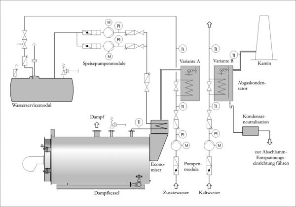
Two-stage flue gas heat recovery systems are employed for calorific value utilisation with a steam boiler. The first economiser, usually integrated into the body of the boiler, cools down the flue gas to approximately 130 °C. A separate, stainless steel flue gas heat exchanger module is then attached downstream in the flue gas flow.
Hot water systems
Up to a few years ago, the main focus of calorific value utilisation was in the area of small condensing and gas boilers for central heating and process water generation in small residential units. In the meantime, heat energy is also used on a larger scale.
The heating system and the actual operating temperatures are the decisive factors influencing the achievable level of calorific value utilisation. Systems in which the heating water is directly circulated through the boiler and the heating element are a basic prerequisite. Furthermore, a variable control principle – in other words, based on atmospheric conditions – should be preferred for the boiler water. Newly planned floor heating systems and large-surface, low-temperature heating elements are particularly suitable for condensing boilers and all-season condensation. As many old systems are equipped with oversized heating elements that generate sufficient heat for most of the heating period, even at lower operating temperatures, they are also suited for use with condensing boilers. Calorific value utilisation is similarly worthwhile for the low-temperature range of heating systems with different temperature zones. In many buildings, heat insulation measures were not implemented until later, which means they can be adequately heated with lower system temperatures. The return flow temperatures suffice for calorific value utilisation for the best part of the year.
Since high-pressure hot water generators for process or remote heating systems with primary heating circuits to heat house substations, as well as connected secondary heating circuits to heat buildings, are usually operated with system return flow temperatures greater than 100 °C, that is to say well above the flue gas dew point, calorific value technology is unsuitable. However, as flue gas heat exchangers are used for “dry” operation, boiler efficiency rates of up to 98 % are feasible. Calorific value can only be utilised in such cases if the system is equipped with a low-temperature secondary circuit.
The highest calorific value utilisation is achieved with the lowest possible return flow temperatures. The system return flow with the lowest temperatures (less than the flue gas dew point of the fuel) flows through the condensation heat exchanger, so that condensation occurs on the exchanger’s heating surfaces. When the flue gases cool down, the low-temperature heating circuit is heated up and supplied to the hot water system again.
The system return flow to the boiler is mixed by the return flow temperature maintenance module with supply flow water to obtain the required minimum temperature of 50 °C before entering the boiler. A special injector in the boiler top ensures efficient throughput and mixing in the boiler. The turn-down ratio of allocated burners, including modulating burners, can be fully utilised. Even in the light and low load range, long burner running times with low flue gas temperatures and optimal calorific value utilisation result. Thanks to the return flow temperature maintenance, boiler water temperatures that are less than the flue gas dew point of the fuel – a potential cause of boiler corrosion – are avoided.
Steam boiler systems
Steam generators with medium temperatures mainly between 150 and 200 °C are supplied with deaerated feed water at a temperature of 85 to 105 °C. The flue gas temperatures of these steam boilers are between 230 and 280 °C for physical reasons. Flue gas heat exchangers are used for feed water heating in order to reduce flue gas losses. During this process, the flue gases are cooled down to approximately 130 °C, in other words still within the ‚dry‘ range above the dew point. It is not possible to utilise calorific value with these energy concepts. By installing a second heat exchanger stage with low-temperature consumers, heat energy can also be utilised with high-pressure steam generators. Like all other downstream flue gas and drainage lines, this flue gas condenser is made of corrosion-resistant stainless steel.
In contrast to building heating systems with clearly definable supply and return flow temperatures, a variety of steam application and heating systems are used in industry. There are consequently many competing energy saving and heat recovery systems. A detailed analysis of all waste heat flows and heat consumers is required in order to identify the most profitable solution. Close cooperation between the operator, planner and boiler manufacturer is essential to determine the most efficient measures from the wide range available.
Steam supply systems recover as much condensate as possible, then return it to the feed water supply of the boiler. However, some systems are unable to recover condensate by direct steam heating or else the condensate contains foreign substances and cannot be reused. There are also losses as a result of desalination, blow-off, re-evaporation and leakage. The loss volumes vary considerably. Far more than half of the total steam generated may be lost and have to be replaced by make-up water. Following water treatment, the make-up water is usually available at a maximum of 15 °C and is excellently suited for preheating in the flue gas condenser. In many industrial applications, particularly in the food industry, there is a high demand for process water. In such instances, the hardness-free service water can be preheated with a flue gas condenser. The water reaches temperatures of around 50 to 70 °C. Further heating of the process water to higher extraction temperatures is possible with a steam-heated heat exchanger located downstream.
Flue gas system
The parts of the housing for the flue gas condenser, as well as flue gas lines and chimneys with a risk of corrosion, are usually made of stainless steel. Extremely low flue gas temperatures down to about 50 °C result from the utilisation of calorific value. The natural chimney pass is not sufficient to discharge the flue gases into the flue gas line efficiently at negative pressure, as is normally the case. The flue gas system, including the chimney, should therefore be designed for overpressure operation on the flue gas side in order to facilitate reduced cross-sections. At the same time, the burner or combustion air fan of the boiler furnace must be capable of overcoming all resistances on the flue gas side.
Condensate drainage
The amount of condensate actually accrued depends on the degree of condensation and mostly ranges from 40 to 60 % of the theoretical amount. If the pH-metric acid value for liquids is taken as a basis, the pH of the flue gas condensate from natural gas combustion is between 2.8 and 4.9 while that from the combustion of low-sulphur fuel oil is between 1.8 and 3.7. The condensate temperature varies between 20 and 55 °C. Municipal sewage regulations must be observed for discharge into the public sewer system. The German Association for Water, Wastewater and Waste (ATV) has issued a technical bulletin recommending a neutralisation unit and adherence to a pH > 6 for all firing systems with calorific value utilisation upward of 200 kW heating capacity. The practical implementation differs substantially from one town or region to another. Small plants can use filters with a renewable dolomite filling (granulate boxes) for neutralisation purposes, whereas containers with dosing devices for caustic soda (liquid neutralisation devices) – which raise the pH accordingly – are more suitable for large plants.
Loos Deutschland marketing@loos.de www.loos.de
Share:

